PMW3610 PCB Rev 2.x
本頁內容尚未翻譯。

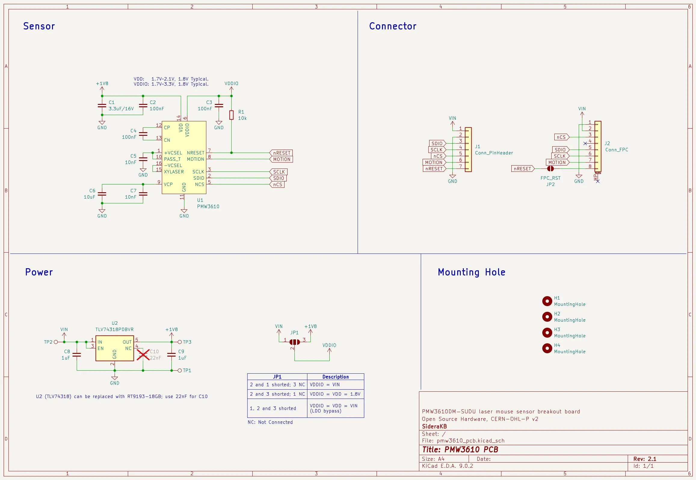
Breakout board for the PixArt PMW3610DM-SUDU, a low-power laser mouse sensor. An alternative to the PMW3360 PCB for low-power applications. Can be used to make a mouse or trackball.
✨ Features:
- Compatible with ZMK projects. Demo video (Rev 1)
- Operates at either 1.8V or 3.3V voltage levels.
- Supports both 2.54mm pin headers and 0.5mm-pitch FFC/FPC connectors.
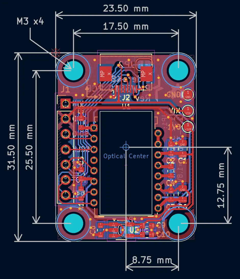
- The optical center of the sensor is located in the center of the PCB.
Online preview available here, powered by KiCanvas.
| Ref | Value | Footprint |
|---|---|---|
| C1 | 3.3μF/16V | SMD 0805* |
| C2, C3, C4 | 100nF | SMD 0603 |
| C5, C7 | 10nF | SMD 0603 |
| C6 | 10μF | SMD 0805* |
| C8, C9 | 1μF | SMD 0603 |
| C10 | DNI | SMD 0603 |
| R1 | 10k | SMD 0603 |
| U1 | PMW3610 | 16-DIP |
| U2 | TLV74318* | SOT-23-5 |
| J1 | 2.54mm Pin header | 2.54mm 1x07 |
| J2 | 8P 0.5mm FFC/FPC | AFC01-S08FCA-00 |
- DNI: Do Not Install.
- SMD 0603 (Imperial) aka 1608 Metric; SMD 0805 (Imperial) aka 2012 Metric.
- The PMW3610 must be used with an LM18-LSI lens.
- The
U2LDO (TLV74318) can be replaced with an RT9193-18GB. If using this replacement, setC10to 22nF. - Recommended capacitor specs:
- Dielectric material: X7R
- Tolerance: +/- 10%
- Rated working voltage: 6.3 ~ 16V
- To accommodate the recommended capacitance values (in μF range),
C1andC6use an 0805 footprint. If the recommended specs aren’t critical for your application, you can opt for an 0603 package instead.
Board Characteristics
Section titled “Board Characteristics”- Copper layer count: 2
- Board thickness: 1.6 mm
- Board overall dimensions: 23.5 x 31.5 mm
- Min track/spacing: 0.15 mm / 0.15 mm
- Min hole diameter: 0.3 mm
- Castellated pads: No
- Edge card connectors: No
- Plated board edge: No
- Mounting hole: M3 x4
Connector
Section titled “Connector”| Pin | J1 PinHeader | J2 FFC/FPC |
|---|---|---|
| 1 | VIN | GND |
| 2 | GND | VIN |
| 3 | SDIO | nCS |
| 4 | SCLK | — |
| 5 | nCS | SDIO |
| 6 | MOTION | SCLK |
| 7 | nRESET | MOTION |
| 8 | — | nRESET |
Voltage Level Config
Section titled “Voltage Level Config”This circuit is designed with a VDD of 1.8V. VDDIO is the voltage used by the IO pin (e.g. SCLK, SDIO), and can be configured for either 3.3V or 1.8V logic.
Most of the current MCU IOs are 3.3V, please use 3.3V Logic config for this MCU. This board does NOT support 5V logic. If using a 5V MCU, please add a level shifter such as the TXS0108E.
| Config | JP1 | VIN Min. | VIN Max. |
|---|---|---|---|
| 3.3V Logic | [1-2 3] | 3.3V | 3.3V |
| 1.8V Logic | [1 2-3] | 2.1V* | 5.5V |
| LDO Bypass* | [1-2-3] | 1.7V | 2.1V |
- 2.1V = 1.8V + 0.3V, where 0.3V is the dropout voltage of the TLV74318 (at Tj ≤ 125ºC).
- Do not install
U2,C8,C9,C10in the LDO Bypass config.
Jumper
Section titled “Jumper”| JP1 | Description | Effect |
|---|---|---|
[1-2 3] | 2 and 1 shorted; 3 NC | VDDIO = VIN |
[1 2-3] | 2 and 3 shorted; 1 NC | VDDIO = VDD = 1.8V |
[1-2-3] | 1, 2 and 3 shorted | VDDIO = VDD = VIN (LDO bypass) |
| JP2 | Effect |
|---|---|
| Shorted | Connects nRESET pin to FFC/FPC |
| Open | Disconnects nRESET pin from FFC/FPC |
- NC: Not Connected.
- JP2 is only available on Rev 2.1.
PMW3610 Spec
Section titled “PMW3610 Spec”The following info is for reference only.
| Parameter | Min. | Typ. | Max. | Unit |
|---|---|---|---|---|
| VDD | 1.7 | 1.8 | 2.1 | V |
| VDDIO | 1.7 | 1.8 | 3.3 | V |
| SCLK Frequency | 2 | MHz | ||
| Working Distance* | 2.2 | 2.4 | 2.6 | mm |
| Operating Temperature | 0 | 40 | ºC | |
| Resolution* | 200 | 3200 | cpi |
- Working Distance is the distance from lens reference plane (i.e. the lowest plane of the lens) to tracking surface (e.g. mouse pad or trackball).
- Resolution with 200 cpi step.
Axis Direction
Section titled “Axis Direction”The raw data direction is defined as:
- X-axis: Right is positive, left is negative.
- Y-axis: Up is positive, down is negative.
However, the Y-axis of the mouse is typically inverted in the OS because the origin is at the top-left corner of the screen. For this reason, the “invert Y-axis” option is commonly enabled.
Firmware
Section titled “Firmware”You can reference the following repo to use PMW3610 PCB with ZMK:
- badjeff/zmk-pmw3610-driver
- inorichi/zmk-pmw3610-driver
- victorlucachi/charybdis-zmk-module
- Real keyboard example:
You can use this sample firmware with the nRF52840-DK to test whether the PMW3610 PCB is functioning properly. Prebuilt firmware can be downloaded from release page.
References
Section titled “References”- GitHub repo: The source design files.
- Release note: You can download Gerber files from here.
- Full changelog